about us
News Center
Your current location:Home - About us - News center
The two figures
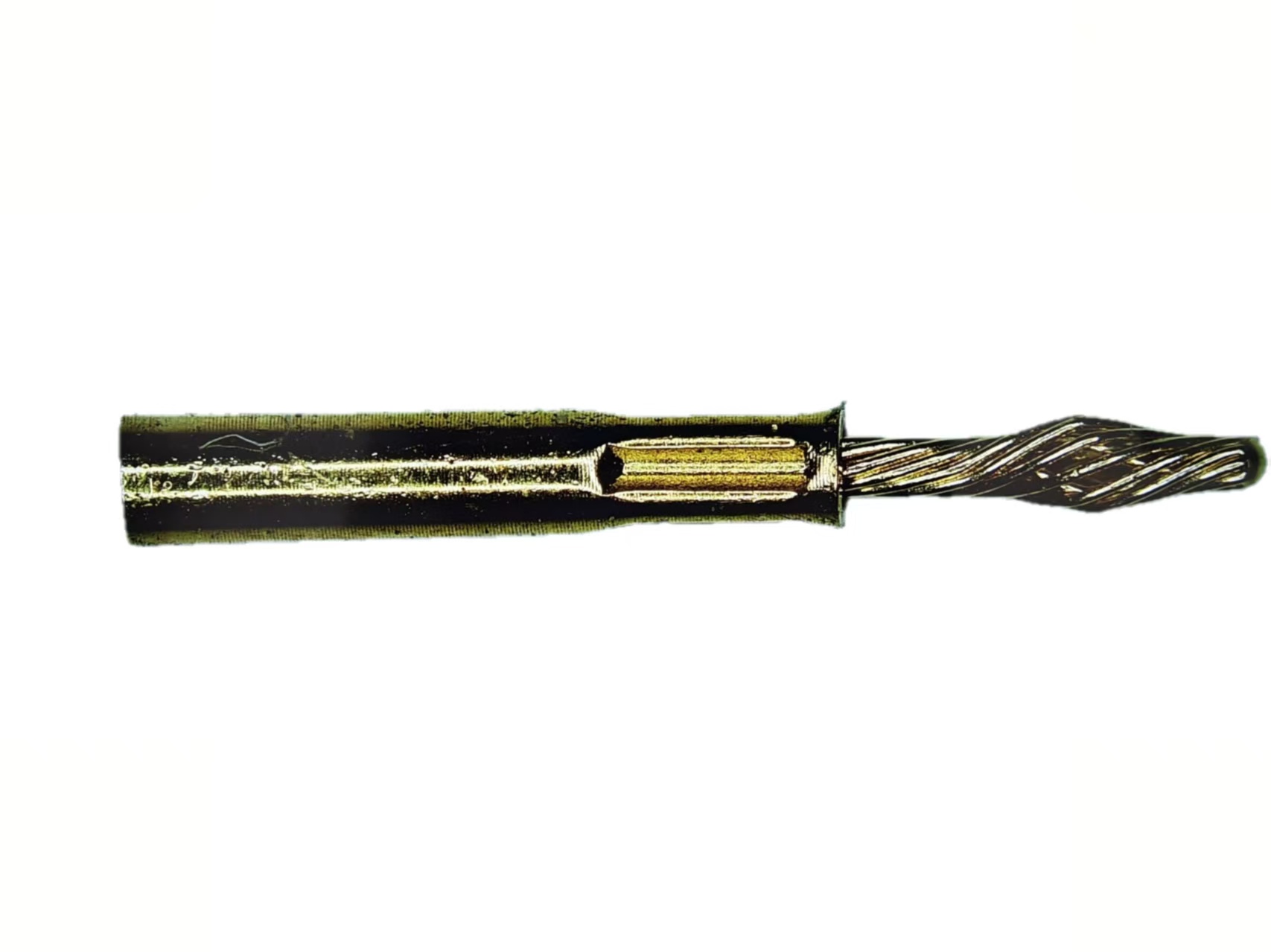
describe opposite halves of the same joint. 0.68mm is the nominal diameter of
the twist pin's wound body, the number that identifies the pin itself. 0.92mm
is the diameter of the receiving bore that the pin enters, which belongs to the
socket half of the pair. Neither figure is useful on its own. 0.68mm tells a
designer the pin envelope but says nothing about how firmly it will sit once
mated. 0.92mm describes the opening without indicating whether anything inside
it will develop reliable contact pressure. Read as a pair, the two numbers
begin to describe a working interface rather than two loose part sizes. The
relationship between the diameters is where the fit actually lives. The gap
between the pin body and the bore is the radial space the twisted strands work
in. Those strands are wound under tension in concentric layers, so when the
pair is mated they deflect outward and press several separate points of the
bore wall instead of one. That elastic deflection is what converts two nominal
diameters into a real electrical joint. It is also why this contact pair is
quoted with a separation force window of 0.25N to 0.8N and a contact resistance
target of ≤10mΩ. Both figures describe the outcome of the pair working
together, not a property of either dimension alone. For layout work, the
practical consequence is that the bore is not simply a hole sized to clear a
0.68mm pin. The pin's working envelope is defined by how far its strands spring
outward under compression, and the bore has to sit inside that envelope for the
pair to generate pressure. That is why a design engineer who needs the
interface to behave consistently should treat 0.68mm and 0.92mm as a single
connected dimension set from the first sketch, not as two entries on a parts
list that can be revised independently.